
I still remember crawling under a customer’s camper van, chasing a smell of hot plastic that turned out to be a 10 AWG wire carrying 35 amps with no fuse anywhere in the run. The previous installer had wired the panels straight to the charge controller, then straight to the battery, trusting it would be fine. It was fine, until it was not.
The quick version
- Every ungrounded conductor in a solar circuit needs overcurrent protection sized to the wire, placed within 7 inches of the power source per ABYC guidance.
- You typically need two fuses or breakers per array: one between panels and controller (PV side), one between controller and battery (load side).
- Fuse size is based on wire ampacity, not on the panel’s or controller’s rated output.
- Use DC-rated breakers or fuses only. AC-rated parts can fail to extinguish a DC arc.
- A busbar with individual branch fuses is the cleanest way to fuse multiple parallel panel strings.
Why solar circuits need fuses in the first place
Solar panels are a little unusual as a power source because they are current-limited by sunlight, not by a short circuit the way a battery is. That confuses people into thinking fusing is less important on the PV side than on the battery side. It is not.
The real danger is not the panel overloading the wire under normal sun. It is a fault: a chafed wire touching the van’s metal frame, a connector that arcs, or two panel strings in parallel where one develops a partial short. In that scenario your battery bank, which can dump hundreds of amps into a dead short, becomes the ignition source even though the panels started the chain.
Fuses protect wire, not equipment. That is the single idea that makes all of this make sense. A fuse exists so that if something goes wrong, the copper melts inside a $8 fuse instead of inside your wall.
Where fuses actually belong in a solar and lithium system
A typical rooftop solar to lithium setup has two separate DC circuits, and each one needs its own protection close to its source.
PV side: panels to charge controller
This fuse or breaker sits as close to the panels as practical, usually right where the roof wire enters the cabin, sized to the wire gauge running down to the controller. If you have two or more panels wired in parallel, each string should get its own fuse before they combine on a common PV positive, so a fault in one string cannot backfeed current from the healthy strings into the fault.
Battery side: charge controller to battery bank
This is the fuse that sees serious fault current, because your lithium bank can supply thousands of amps for a brief moment into a dead short. It goes within about 7 inches of the positive battery terminal or busbar, sized to the wire between controller and battery, per ABYC E-11 recommendations for DC systems.
Warning: Never skip the battery-side fuse because you already fused the PV side. These are two separate circuits protecting two separate wire runs, and a fault downstream of the controller will not be caught by a PV fuse upstream of it.
Sizing the fuse correctly
Fuse sizing trips people up because they size to the equipment instead of the wire. Here is the actual process I use on every build.
- Determine the maximum current the wire will realistically see (panel Isc times 1.25 for the PV side, or controller max output for the battery side).
- Choose wire gauge that comfortably exceeds that current with margin for voltage drop over your run length.
- Size the fuse to protect the wire’s ampacity rating, landing between the expected operating current and the wire’s maximum safe current.
As a real example: two 200W panels wired in parallel might produce a combined short-circuit current around 22A. Multiply by the standard 1.25 safety factor and you are sizing wire for about 27.5A, which points to 10 AWG wire, with a 30A fuse fitting comfortably.
On the battery side, a Victron SmartSolar 100/30 controller maxes out at 30A of charge current. Running that through 8 AWG wire, rated well above 30A continuous, a 35A or 40A fuse is typical, again matching the wire rather than the controller’s number.
Tip: When in doubt, oversize the wire slightly and undersize nothing. Cheap 10 AWG wire is a lot less expensive than a diagnosis session six months from now chasing intermittent voltage drop.
Fuse types and where each one makes sense
| Fuse/breaker type | Typical use | Notes |
|---|---|---|
| MRBF (battery terminal fuse) | Directly on battery terminal or busbar | Fast, compact, common on Blue Sea Systems battery banks |
| ANL fuse | Mid to high current inline, PV or battery side | Rated up to 300A+, needs a proper ANL fuse holder |
| MIDI/AMI fuse | Common on smaller controller-to-battery runs | Compact, blade-style, easy to source at auto parts stores |
| DC-rated breaker | PV or battery side where a manual disconnect is wanted | Resettable, doubles as a switch, must be DC-rated specifically |
I lean toward a breaker on the battery side of most of my own builds now, mainly because it lets me kill power for maintenance without hunting for a spare fuse in a drawer somewhere.
A mistake I see constantly
The single most common error is mismatched fuse and wire ratings, usually because someone reused a fuse holder from a different project without rechecking the math. I have seen a 60A ANL fuse sitting on 10 AWG wire, which defeats the entire purpose since the wire will overheat and fail well before that fuse ever thinks about blowing.
The second most common mistake is fusing both conductors instead of just positive. Standard practice, and what ABYC recommends for mobile DC systems, is to fuse the positive conductor only, with negative bonded to a common ground bus. Fusing negative too can create confusing failure modes, so stick with positive-side fusing unless your system design calls for something different.
Grounding and bonding basics
Solar panel frames should bond to the vehicle or vessel’s common ground point, separate from your current-carrying negative wire. This protects against a chafed wire energizing the panel frame and turning your roof into a shock hazard. Most aluminum panel frames have a grounding lug built in for exactly this purpose, and a short run of 10 AWG green or bare wire to your chassis ground point handles it.
Your MPPT controller’s negative output typically lands on the same busbar as your battery negative and shunt. Check the specific wiring diagram for your controller, since Renogy, Victron, and Xantrex lay out their terminals slightly differently.
Putting it together on a real system
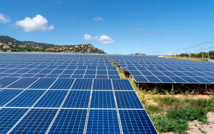
A clean example: 400W of rooftop solar, split into two strings, feeding a Victron SmartSolar 100/30, charging a 200Ah Battle Born or Li Time lithium bank. Each panel string gets a 15A inline fuse near the roof penetration, and the combined PV positive runs 10 AWG down to the controller. The controller’s battery output runs 8 AWG about 4 feet to the battery busbar, protected by a 40A MRBF fuse mounted right on the busbar.
That is four total protection points for one array, and every single one of them is sized to the wire it protects rather than to a round number that seemed reasonable. If you are still working out your broader charging setup, it is worth reviewing our full solar charging setup guide for lithium before you finalize your fuse and wire schedule, since panel configuration affects every number above.
If you have not settled on controller size yet, our guide on how to size an MPPT controller walks through matching controller amperage to your array, which directly determines your battery-side wire and fuse. And once the system is running, a look at proper solar controller settings for LiFePO4 ensures the fusing you just installed is actually protecting a charge profile that is right for your battery chemistry.
For an authoritative reference on marine and mobile DC electrical standards, the American Boat and Yacht Council publishes the E-11 standard that most of these fusing and grounding practices are drawn from, and it is worth a read even if you never plan to have your rig inspected.
Wiring solar safely is not about buying the fanciest gear, it is about matching every fuse to the wire behind it and putting each one close to its power source. Do that consistently on both the PV side and the battery side, use DC-rated components throughout, and you will have a system that quietly protects itself instead of becoming the next van fire story on a Facebook group.